Create lens calibration data for lensfun
Adding support for your lens

Adding support for your lens
[Article updated on: 2019-12-09]
All photographic lenses have several types of errors. Three of them can be corrected by software almost losslessly: distortion, transverse chromatic aberration (TCA), and vignetting. The Lensfun library provides code to do these corrections. Lensfun is not used by the photographer directly. Instead, it is used by a photo raw development software such as darktable or RawTherapee. For example, if you import a RAW into darktable, darktable detects the lens model, focal length, aperture and focal distance used for the picture, and it then calls Lensfun to automatically correct the photograph.
Lensfun uses a database to know all the parameters needed to do the lens corrections. This database is filled by photographers like you, who took time to calibrate their lenses and to submit their findings back to the Lensfun project. If you’re lucky, your lens models are already included. If not, please use this tutorial to do the calibration and contribute your results.
Let us assume your lens isn’t covered by Lensfun yet, or the corrections are either not good enough or incomplete. The following sections will explain how to take pictures for calibration. It will also show you how to create an entry of your own. The best is to provide information for all three errors but maybe you only need distortion then this is fine too.
Before you start to calibrate new lenses or report missing cameras please check the lens database first! The list is updated daily. If your lens is already support then everything is fine and you just have to update your database.
If the lens is not supported or doesn’t provide all corrections you could add the missing data following this tutorial.
Before we start you need to take a lot of images for the three errors we are able to correct. This section will explain how to take them and what you need to pay attention to.
For all pictures you should use a tripod, turn off all image correction and disable image stabilization in the camera and in the lens itself! Also make sure to that all High Dynamic Range (HDR) or Dynamic Range Optimizer (DRO) features are turned off. All those options could mess up your calibration.
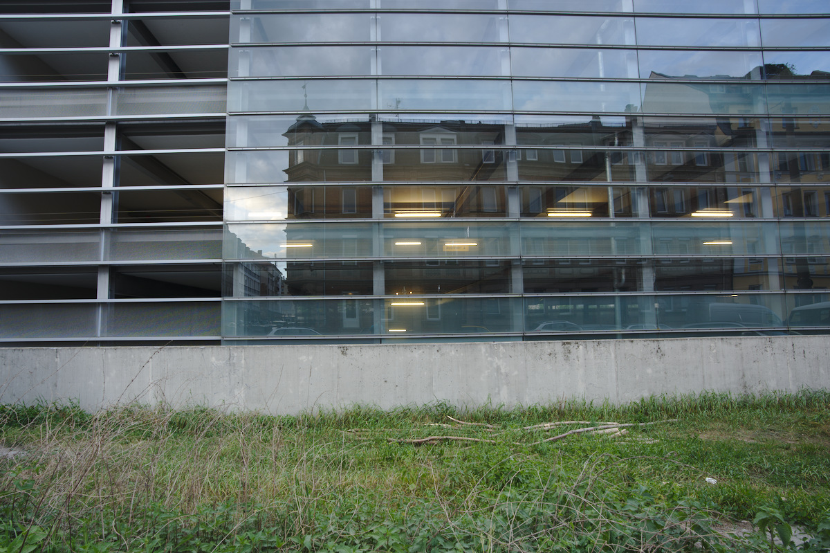
For distortion you can to take pictures of a building with several parallel straight lines. You need at least two lines, one should be at the top of the image (Nearly touching the top of frame) and the other line at about a third down from the first line. The following example demonstrates this.

The lines must be perfectly straight and aligned. You can twist and rotate the camera, but the lines must have no imperfections. Common mistakes are using tiles or bricks: to your eye they may be “straight”, but it will cause calibration defects. The best buildings turn out to be parking houses (US: parking lot, EN: garages, car parks) or modern glass buildings like fruit-technology stores.
For a fixed focal length lens, you only will require one image. For a zoom lens it is recommended to take 5 to N pictures where N is max focal length minus min focal length. You must take an image at the minimum focal length, and the maximum focal length. You can move (step backward on forward) between shots to keep the 1/3rd rule above consistent.
You should shoot at your lenses sharpest aperture - this is often f/8 to f/11. Setup your camera on a tripod. Shoot at the lowest ISO (without extended values). This will be 100 or 200. Disable any inbody lens corrections. Every vendor has a different name for this process (Fuji is modular lens optimization for example). Check your camera manual and menus.
For TCA images look for a large object with sharp high-contrast edges throughout the image. Preferably, the edges should be black–white but anything close to that is sufficient. Make sure that you have hard edges from the center throughout to one of the edges. The best buildings, for taking photos, have dark windows with white or gray frames.
Here are some example pictures:
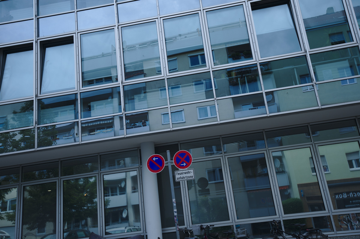
You should take your pictures being at least 8 meters away. For zoom lenses, take pictures at the same focal lengths as for distortion (5 to N). Make sure to capture really sharp photos using at least f/8. The best is to use aperture control, f/8 and ISO 100 on a tripod to avoid any color noise.
You can use e.g. a streetview service to find the right building in your town (big buildings, dark windows with white or grey frames).
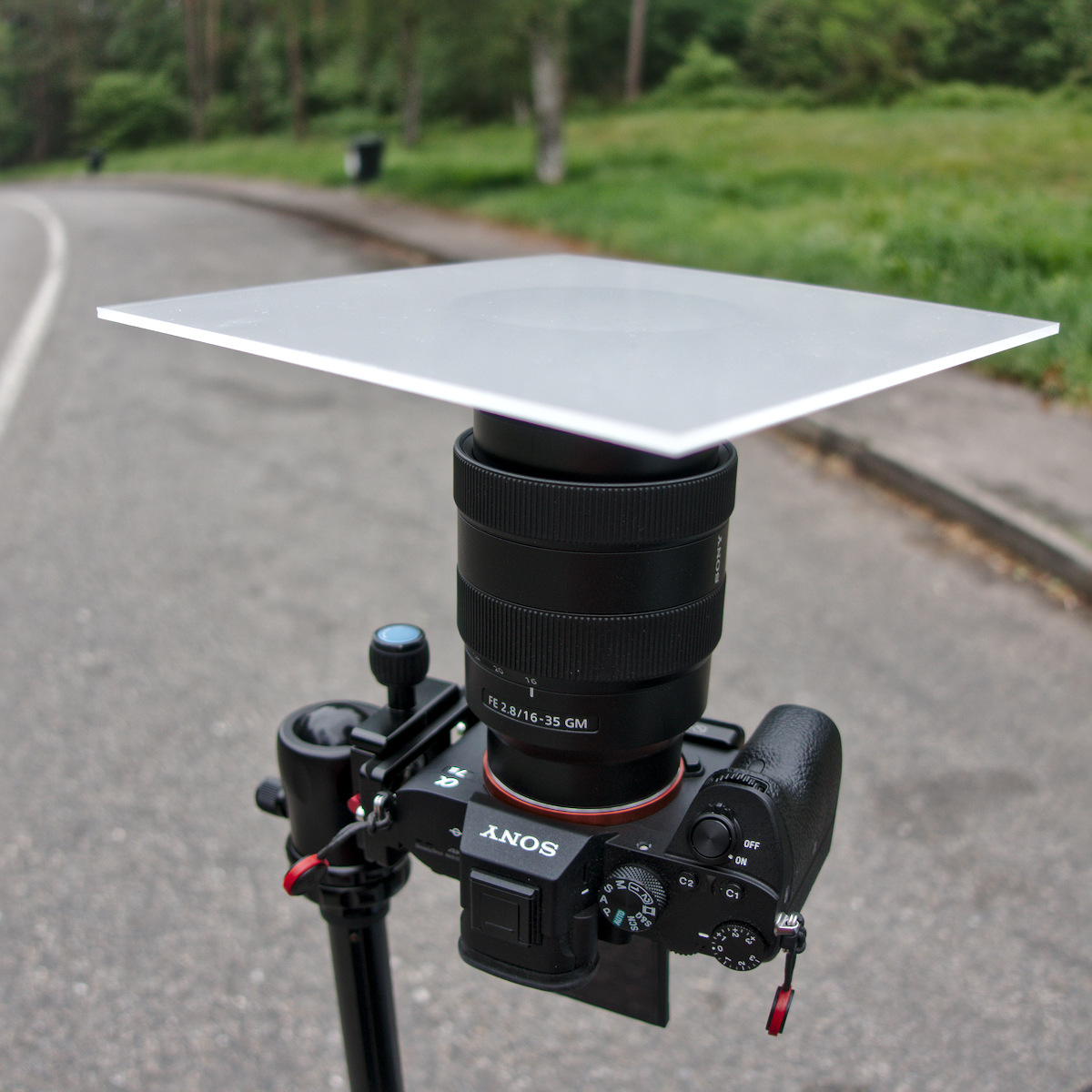
To create pictures for vignetting you need a diffuser in front of the lens. This may be translucent milk glass, or white plastic foil on glass. Whatever, as long as it is opaque enough so that nothing can be seen through it, yet transparent enough so that light can pass through it. It must not be thicker than 3 mm and shouldn’t have a noticeable texture. It must be perfectly flush with the lens front, and it mustn’t be bent. It must be illuminated homogeneously.
I ordered a piece of acryl glass, opal white (milky), smoothly polished, 78% translucency, 3mm thick, 20 x 20 cm, which is about 8 Euro on Amazon.
However white plastic foil taped on a piece of ordinary glass for stability might be enough, if the plastic doesn’t have any texture.
I normally wait for a cloudy day with no sun, then the sky is homogeneously lit. Put the camera on a tripod and point it to the sky. Put the glass directly on the lens (remove any filters). In some places where sunlight is different you may need to shoot indoors. You should experiment to make sure your images are evenly lit (except for vignetting obviously).

Make sure that no corrections are applied by the camera (some models do this even for RAWs). Set the camera to aperture priority and the lowest real ISO (this is normally 100 or 200, don’t use extended ISO values).
Switch to manual focus and focus to infinity. This is the most critical step!
For zoom lenses, you need to take pictures at five different focal lengths. You only need pictures for five focal lengths because for the other steps it gets interpolated. For a prime lens you need to take only pictures for the single focal length.
Take the pictures as RAW at the fastest aperture (e.g. f/2.8) and at three more closed apertures at 1 EV distance, and also at the most closed aperture (e.g. f/22.0). These are often marked on your lens’ aperture ring, or on your electronic display.
If you have for example a 16-35mm lens with aperture f/2.8 - f/22, you need to take pictures at 16mm, 20mm, 24mm, 28mm and 35mm focal length (Remember you require the min and max zoom values). For each for those focal lengths you need to take five pictures at f/2.8, f/4.0, f/5.6, f/8.0 and f/22.0. This makes 25 pictures in total.
For a 50mm prime lens with f/1.4 - f/16 you need to take 5 pictures at f1.4, f/2.0, f/2.8, f/4.0, and f/16.0.
For taking the picture the middle of the area needs to be as bright as possible, but not overexposed. This can be easily +1.7 to +2.0 EV.
If your camera has a zebra setting, turn it on and set the zebra mode to ‘100’. If you start to see the zebra, then take the picure. The profile is created on a RAW file and the zebra is shown for a developed picture. So we aren’t overexposed yet. In the control mode in my camera which shows overexposure everything was fine.
The following steps are to get really fine grained vignetting corrections. The gain in accuracy is really very small! I probably only makes sense for prime lenses used for portrait or macro photography. However this is not required, the above it absolutely enough.
Lensfun is able to correct vignetting depending on focal distance. Thus, you can achieve a bit more accuracy by shooting at different focal distances. This means you will have to take pictures at 4 different focal distances.
The first focus on the near point (The near point is the closest distance that can be brought in focus). The next focal distances are the near point multiplied by 2 and by 6 and finally focus at infinity.
Example: For a 85mm prime lens with the near point at 0.8 m. You have to take pictures at 0.8 m, 1.6 m, 4.8 m and infinity.
There are two ways to perform the calibration.
Lensfun allows an upload of data to the project, and they’ll do the program work for you. They’ll also review your images to make sure they are correctly taken.
Or you can do it yourself with the lens calibration script from the lensfun project.
The script needs the following dependencies to be installed on your system:
You can download the lens calibration script HERE or get it as a package for the major distributions HERE.
Once you have downloaded the tool create a folder for your lens calibration data, change to the directory and run:
$ lens_calibrate.py init
The following directory structure has been created in the local directory

1. distortion - Put RAW file created for distortion in here
2. tca        - Put chromatic abbreviation RAW files in here
3. vignetting - Put RAW files to calculate vignetting in here
Follow the instructions and copy your raw files in the corresponding directories.
For each focal distance you captures pictures you have to create a folder.
Lets pick up the example from above. For a 85mm prime lens we took pictures at 0.8 m, 1.6 m, 4.8 m and infinity. For this lens you would have to create the following folder structure in the vignetting directory:
vignetting/0.8
vignetting/1.6
vignetting/4.8
vignetting/inf
The folder inf is for the focal distance at infinity.
Once you copied the files in place it is time to generate the pictures (tif files) for distortion calculations. You can do this with the ‘distortion’ option:
$ lens_calibrate.py distortion
Running distortion corrections ...
Converting distortion/_7M32376.ARW to distortion/exported/_7M32376.tif ... DONE
A template has been created for distortion corrections as lenses.conf.
Once the tif files has been created, you can start Hugin.
Torsten Bronger created a screen cast to give an overview about the distortion process in Hugin. He uses an old Hugin version in the video. The following section of this tutorial explains how to do it with Hugin 2018. You can watch the screen cast first if you want, you can do it here (Vimeo).
If you start Hugin the first time, the windows you will get should look like in Figure 8.
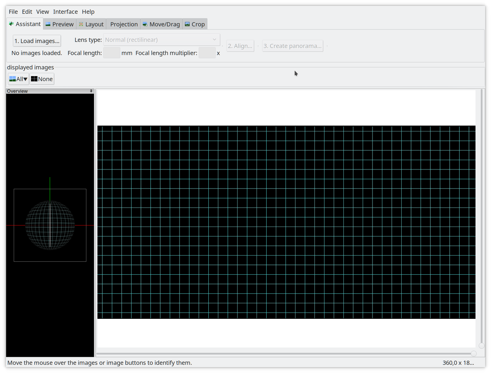
First select on the menu bar Interface -> Expert to switch to the Expert mode. You will get a windows which should look like as in Figure 9.
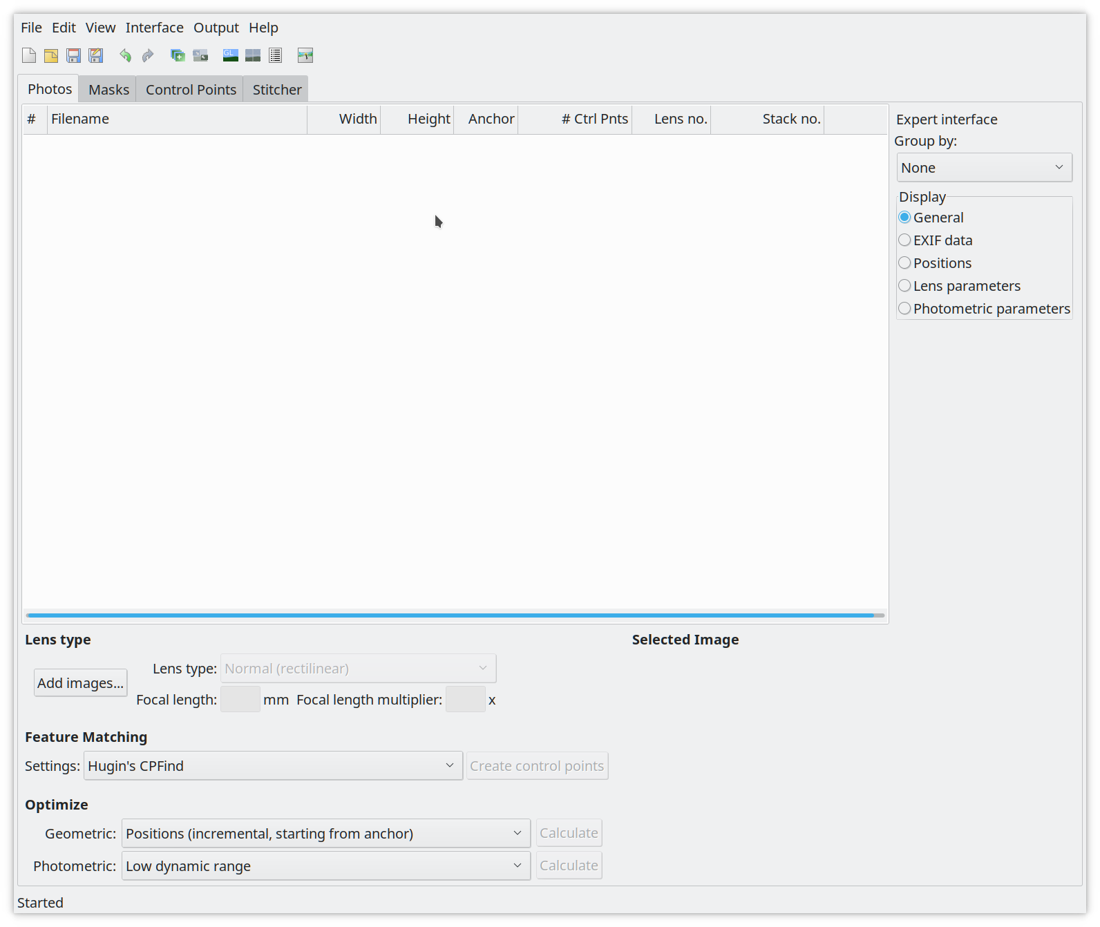
Once in the export mode click on Add images (Figure 10) and load the first tiff from the distortion/exported folder.
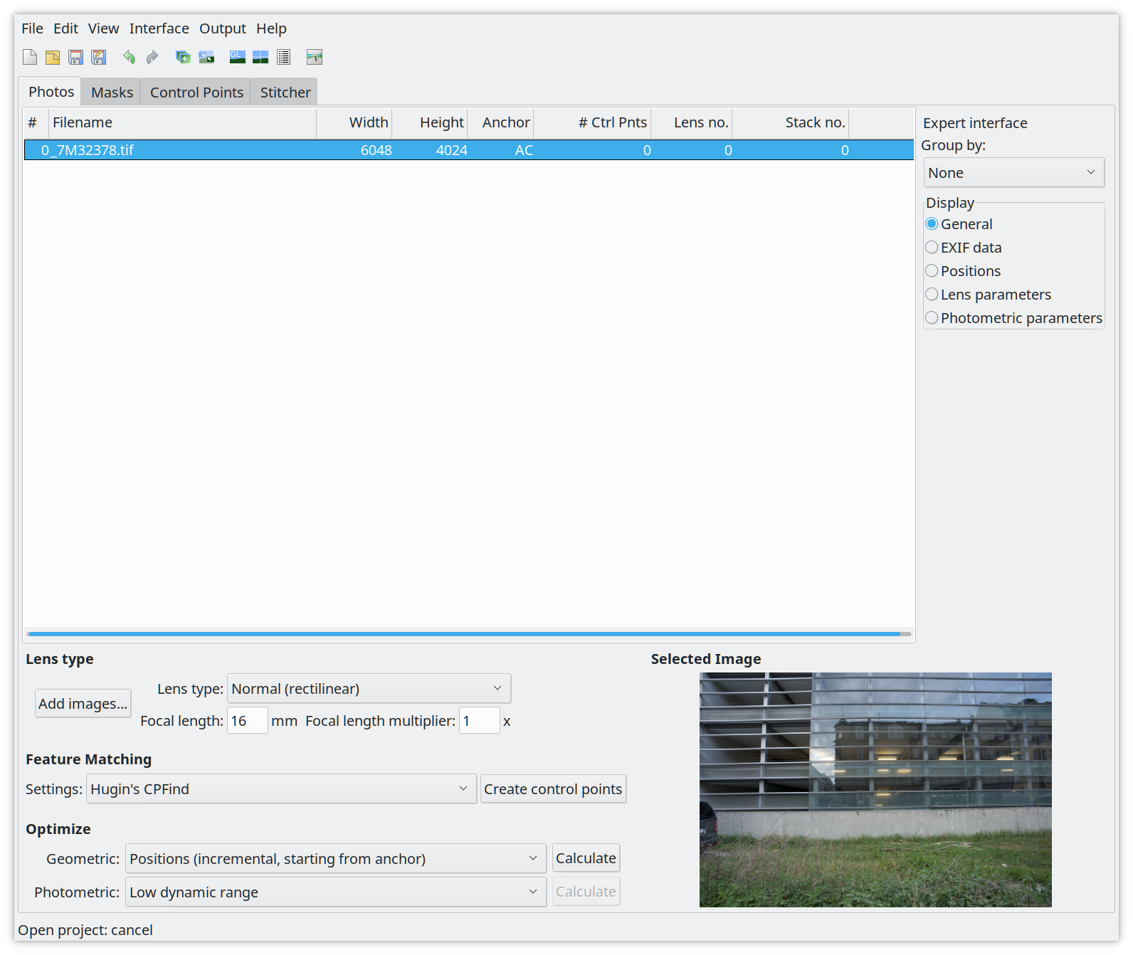
By default the lens type should be set to Normal (rectiliniar) for normal standard lenses. Make sure that the focal length is correct and set the Focal length multiplier, which is the crop factor of your camera. For full frame bodies this value should be 1. If you have a crop camera you need to set the correct crop value you can find in the specifications. Next click on the Control Points tab (Figure 11).
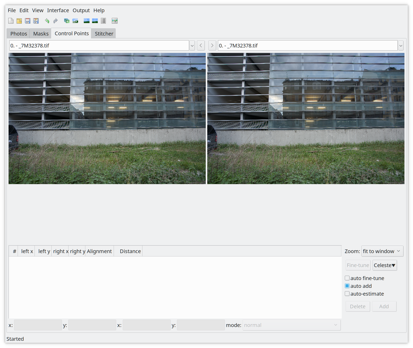
This is the tab to set the control points so that we can tell the software what are our straight lines we are interested in. In this tab you have to make sure that auto fine-tune is disabled, auto add is enabled and auto-estimate is disabled! If this is the case zoom the image to 200% (you can also do this by pressing ‘2’ on the keyboard).
In the zoomed images you have start at the top edges. On the left go to the top left corner and to the top right corner on the right. The first straight line, from left to right, should be visible. Select the first control point on the left edge of the picture on the left page and the right edge on the right (Figure 12).
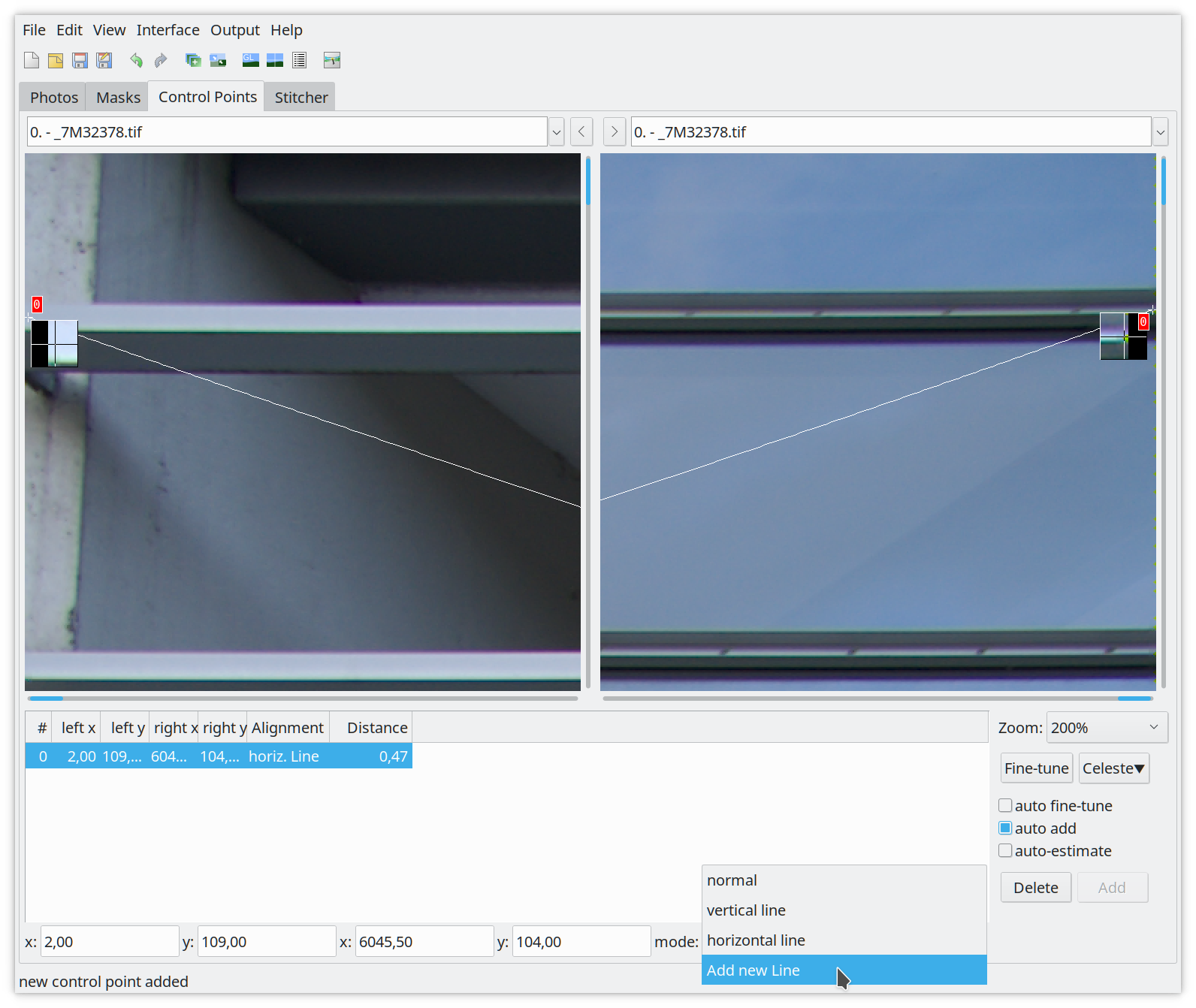
IMPORTANT: Once you have the first control point selected in both images. Select Add new Line in the mode dropdown menu! This will add the two control points as line 3! Now continue adding corresponding control points in both pictures till you’re in the middle on both sides.
Tip: The easiest and fasted is to set control points in the middle at the tiling line. This reduces the required mouse movements.
Now zoom out by pressing ‘0’ and check it if everything has been added correctly (Figure 13).
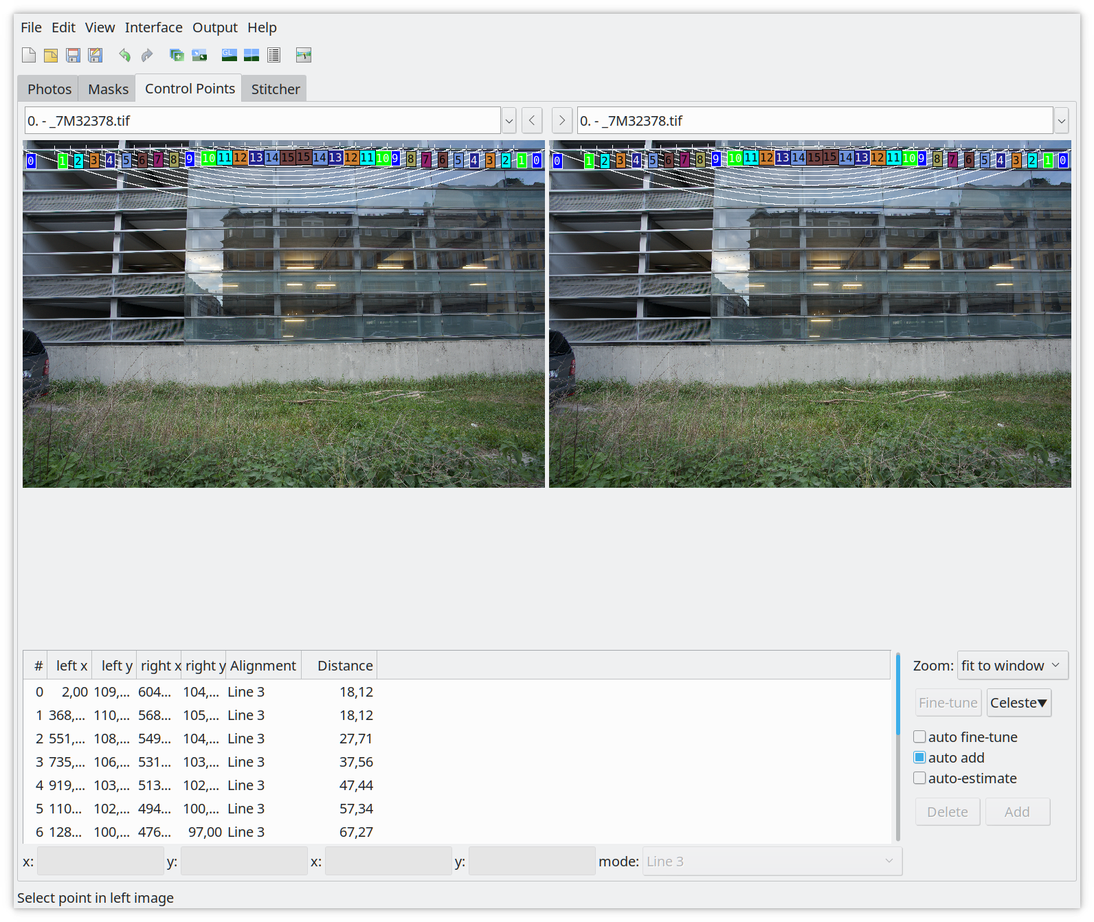
While you are zoomed out, find a line which is about 3rd into the image from the top to repeat adding a line. Zoom to 200% again, select the first control points and again Add a new line which will result in line4 (Figure 14)!
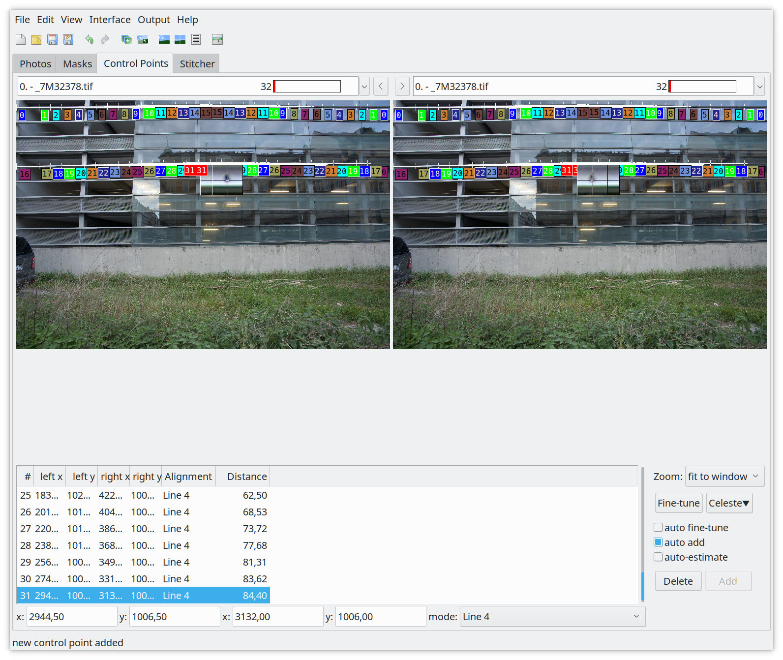
Zoom out by pressing ‘0’ and check that you have two lines, line3 and line4. Now move on to the Stitcher tab (Figure 14).
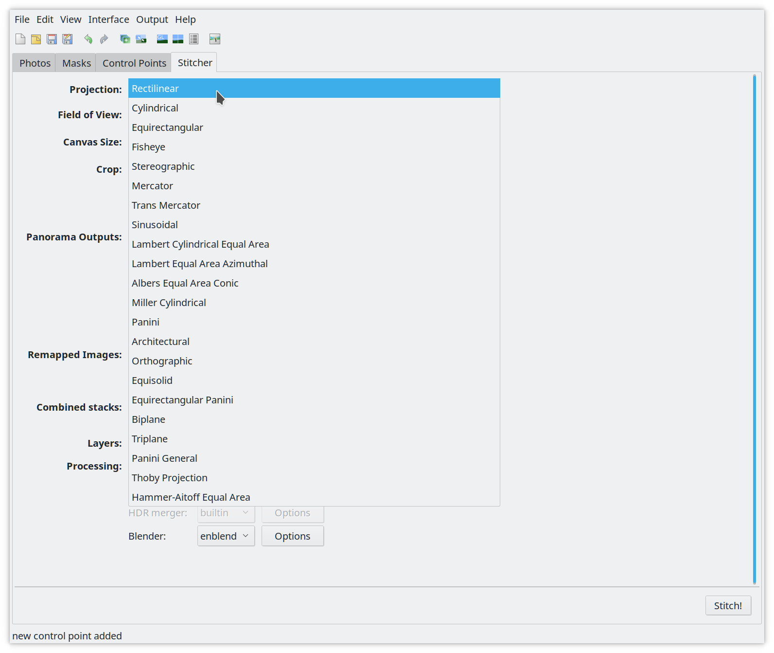
In the Stitcher tab you need to select the correct Projection for your lens. This is Rectilinear for standard lenses. Once done switch to the Photos tab (Figure 16).
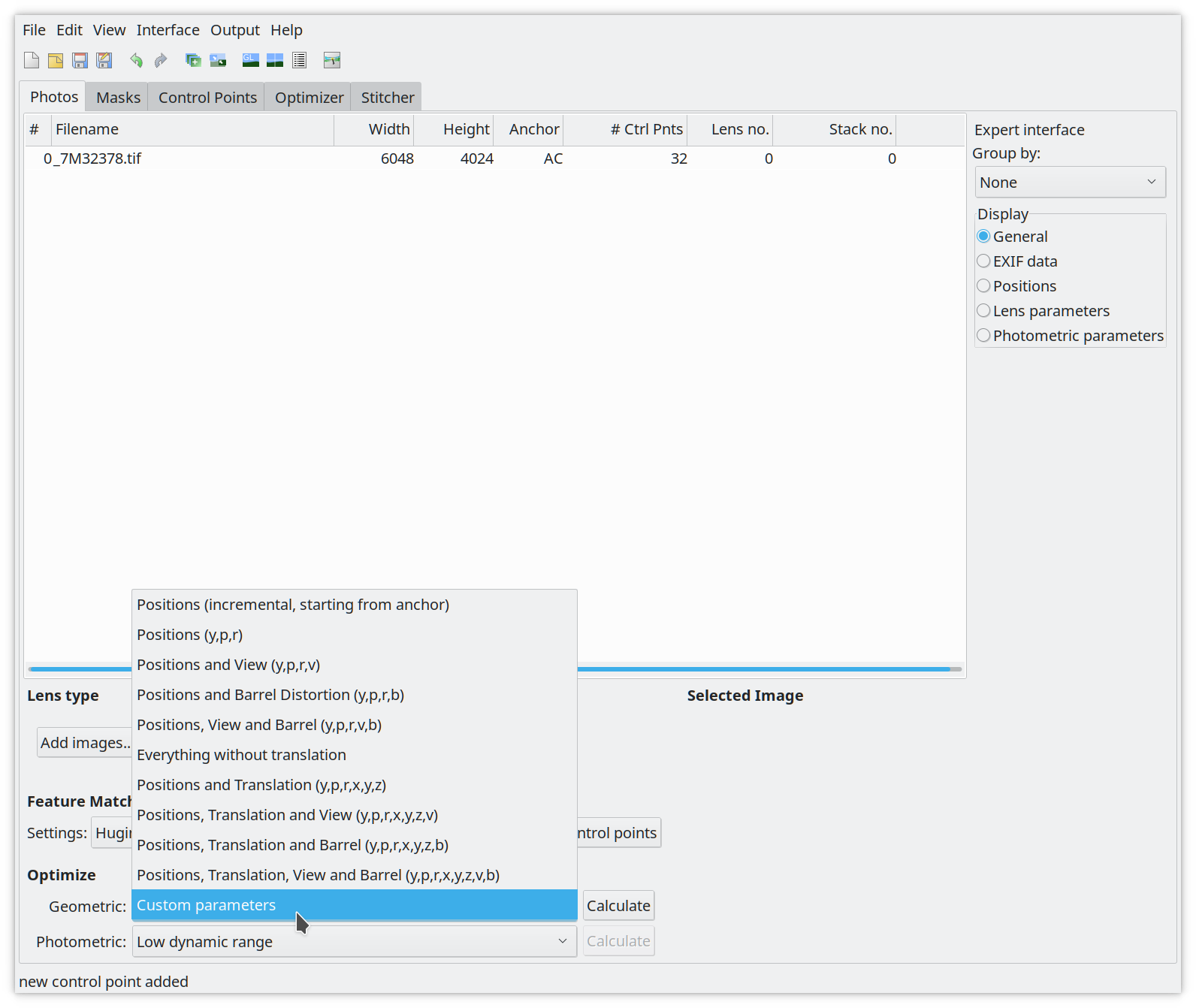
At the bottom under Optimize select Custom parameters for Geometric. This will add an Optimizer tab. Switch to it once it appears (Figure 17).
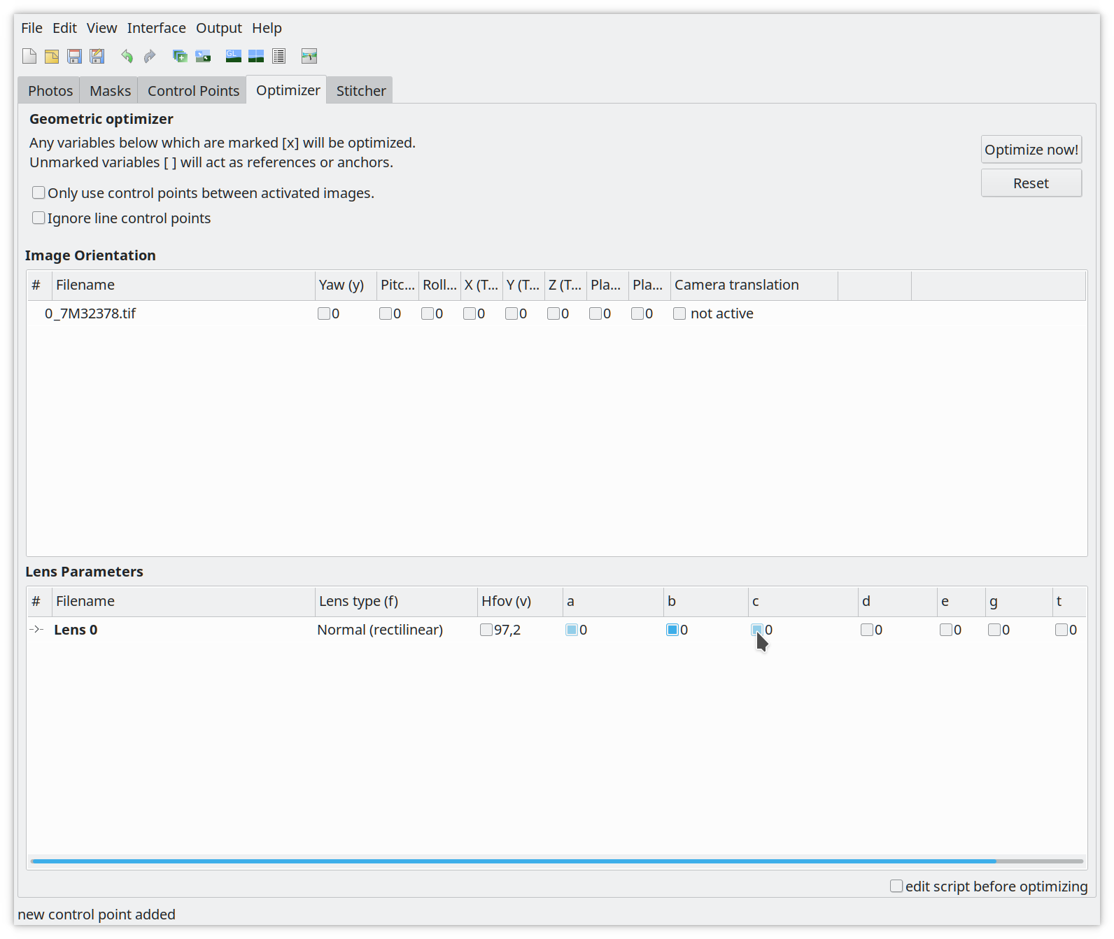
Select the ‘a’, ‘b’ and ‘c’ lens parameters and click on Optimize now!. Accept the calculation with yes. Now the values for ‘a’, ‘b’ and ‘c’ will change (Figure 18).
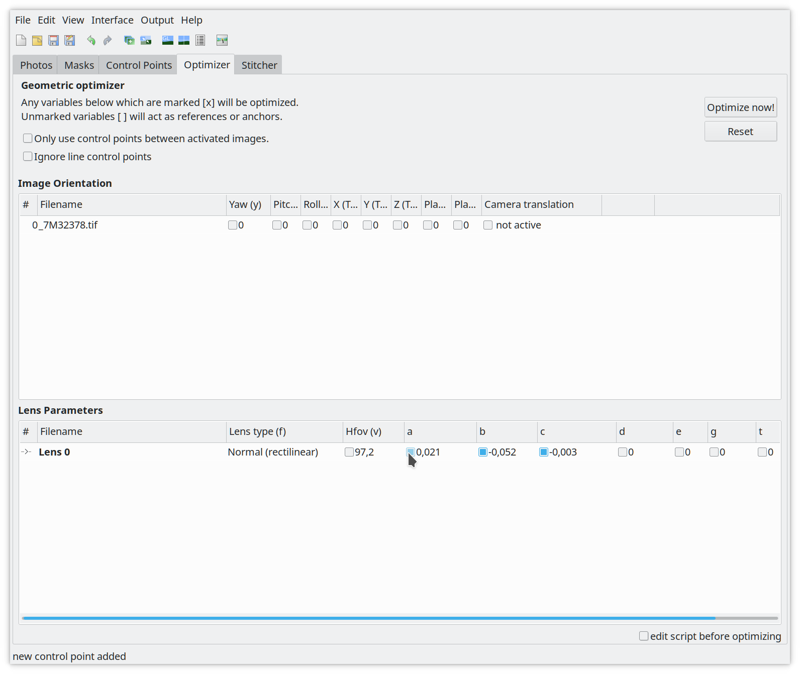
The calculated correction values for ‘a’, ‘b’ and ‘c’ you can find in the tab need to be added to the lenses.conf. Open The file and fill out the missing options. Here is an example:
Example:
[FE 85mm F1.4 GM]
maker = Sony
mount = Sony E
cropfactor = 1.0
aspect_ratio = 3:2
type = normal
maker is should be the lens manufacturer e.g. Sonymount is the mount system for the lens, check the lensfun databasecropfactor is 1.0 for full frame cameras, if you have a crop camera find out the correct crop factor for it.aspect_ratio is the aspect ratio for the pictures which is normally 3:2.type is the type of the lens, e.g. ‘normal’ for standard rectilinear lenses. Other values are: stereographic, equisolid, stereographic, panoramic or fisheye.If you have e.g. a 85mm there should be an entry for the focal length which is set to: 0.0, 0.0, 0.0. You need to change the values in the lenses.conf for your focal length with the calculated corrections from the Optimizer tab (Figure 16).
[FE 85mm F1.4 GM]
maker = Sony
mount = Sony E
cropfactor = 1.0
aspect_ratio = 3:2
type = normal
distortion(85mm) = 0.002, 0.001, -0.009
No problem, if you want to skip this step then you can created the lenses.conf manually. It should look like the following example:
[lens model]
maker =
mount =
cropfactor = 1.0
aspect_ratio = 3:2
type = normal
The section name is the lens model. You can find it out by running:
exiv2 -g LensModel -pt <raw image file>
The other options are:
maker is should be the lens manufacturer e.g. Sonymount is the mount system for the lens, check the lensfun databasecropfactor is 1.0 for full frame cameras, if you have a crop camera find out the correct crop factor for it.aspect_ratio is the aspect ratio for the pictures which is normally 3:2.type is the type of the lens, e.g. ‘normal’ for standard rectilinear lenses. Other values are: stereographic, equisolid, stereographic, panoramic or fisheye.You can skip this step if you don’t want to do TCA corrections.
This step is fully automatic, all you have to do is to run the following command and wait:
$ lens_calibrate tca
Running TCA corrections for tca/exported/_7M32375.ppm ... DONE
However it possible to calculate more complex TCA corrections. For this you need to run the step it with an additional command line argument, like this:
$ lens_calibrate --complex-tca tca
Running TCA corrections for tca/exported/_7M32375.ppm ... DONE
You can skip this step if you don’t want to do vignetting corrections.
To calculate the vignetting corrections it is also a very simple step. All you have to do is to run the following command and wait:
$ lens_calibrate vignetting
To get corrections for lensfun you need a lenses.conf with the required options to be filled out (maker, mount, cropfactor, aspect_ratio, type). And at least one of the corrections steps done. If you have this you can generate the XML file which can be consumed by lensfun. You can do it with the following command:
$ lens_calibrate generate_xml
Generating lensfun.xml
You can redo this step as many times as you want. And you can just rerun it if you add an additional correction.
You may want to fine-tune the lens model name in the generated lensfun.xml
file. Lensfun normalises names before any matching, so you have some freedom.
For example, upper/lowercase can be changed arbitrarily. Any single f is
ignored, so you may change 16-35mm 2.8 into 16-35mm f/2.8. If there was a
tele converter involved, you must add “converter” into the name so that Lensfun
does not try to derive allowed focal lengths from the lens name.
Ordering of parts in the lens name is completely unimportant for matching. As
are single punctuation characters. You may even add things (e.g. 16-35 into
16-35mm) but be conservative here. Never drop anything what exiv2 reports!
If you want to use the generated lensfun.xml file to test if the calibration you created works, you can copy to the local lensfun config folder in your home directory.
cp lensfun.xml ~/.local/share/lensfun
Make sure your camera is recognized by lensfun or you need to add an entry to the lensfun.xml file too.
To contribute your calibration data data for your lens to the lensfun project, execute the script with the following command:
$ lens_calibrate ship
Created lensfun_calibration.tar.xz
Open a bug at https://github.com/lensfun/lensfun/issues/ with the data.
This will create a tarball with all the required data. Now go to
and open a bug using the following subject:
Calibration data for <lens model>
And for the description just use:
Please add the attached lens data to the lensfun data base.
Attach the lensfun_calibration.tar.xz to the bugreport.
Feedback for this article is very welcome. If you’re a lensfun developer and read this please contact me. I would like to contribute the script to lensfun and further improve the article. I still have unanswered questions.
